Very Basic Arduino Uno Board Testing

A very simple Arduino board test... LOL

Here is some very easy code to test a cheap Arduino board I just got from China via Aliexpress. I am still waiting on a about 30 more orders from Aliexpress for more Arduino stuff. This was the first order which made it here.

/* 
Arduino test-code
This code is intended to be used for an easy introduction to the Arduino board. 
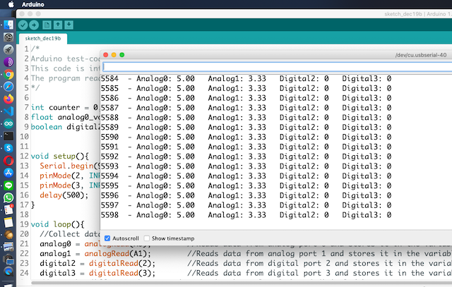
The program reads data from 2 digital and 2 analog ports and prints the values to the monitor with a sampling speed of 1 Hz.
*/

int counter = 0, analog0, analog1; //Creates variables as integers
float analog0_volt, analog1_volt;  //Creates variables as floating numbers.
boolean digital2, digital3;        //Creates variables as boolean (HIGH or LOW, TRUE or FALSE)

void setup()
{                             //Setup. This section runs only once.
    Serial.begin(9600);       //Sets the communication speed between PC and Arduino Uno to 9600 baud.
    pinMode(2, INPUT);        //Sets the digital 2 pin to input mode (High impedance).
    pinMode(3, INPUT_PULLUP); //Sets the digital 2 pin to input mode with "Pull Up" (High impedance and Normal High).
    delay(500);               //0.5 seconds break.
} //end of setup

void loop()
{ //Loop. This section runs in an unending loop.
    //Collect data from all the inputs
    analog0 = analogRead(A0);  //Reads data from analog port 0 and stores it in the variable "analog0".
    analog1 = analogRead(A1);  //Reads data from analog port 1 and stores it in the variable "analog1".
    digital2 = digitalRead(2); //Reads data from digital port 2 and stores it in the variable "digital2".
    digital3 = digitalRead(3); //Reads data from digital port 3 and stores it in the variable "digital3".
    //Note the difference between pin numbering in analog (Ax) and digital (x).

    //Convertion from digital value to voltage value
    analog0_volt = ((float)analog0 / 1023) * 5; //Scales from 0-1023 (integers) to 0.0-5.0 (decimal numbers). 0=0V 1023=5V.
    analog1_volt = (analog1 / 1023.0) * 5;      //Does the same as the previous line. Notice the difference in the syntax.

    //Print out data to the monitor
    Serial.print(counter);         //Prints out the variable "counter".
    Serial.print("  - Analog0: "); //Prints the text inside the brackets "__".
    Serial.print(analog0_volt);    //Prints out the variable "analog0_volt".
    Serial.print("   Analog1: ");  //Prints the text.
    Serial.print(analog1_volt);    //Prints out the variable "analog1_volt".
    Serial.print("   Digital2: "); //Prints the text.
    Serial.print(digital2);        //Prints out the variable "digital2".
    Serial.print("   Digital3: "); //Prints the text.
    Serial.println(digital3);      //Prints out the variable "digital3" and ends with a line shift.

    delay(1000); //A 1000ms delay.
    counter++;   //Increments the variable "counter".

} //end of function (Returns to start of loop).

//The program inside the loop function will continue forever and ever, or until power down.

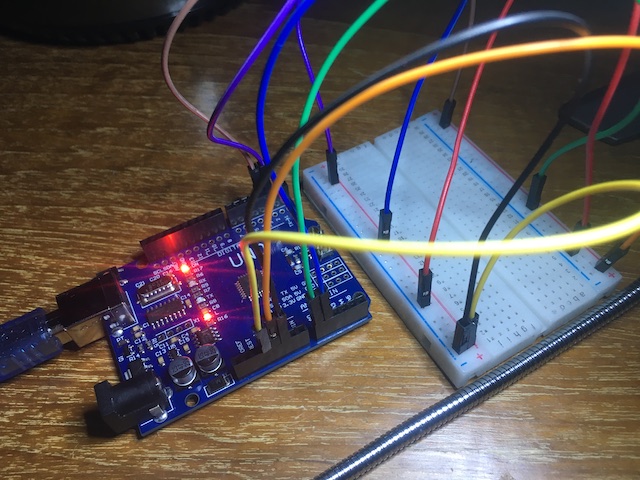
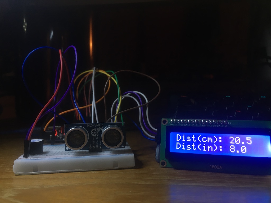
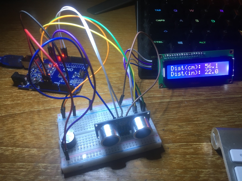
Using the Arduino IDE on the mac I uploaded the code above into my new cheap Chinese Arduino board and set up a simple test before I get into some more interesting stuff.

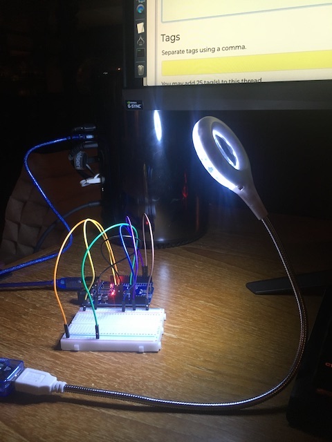
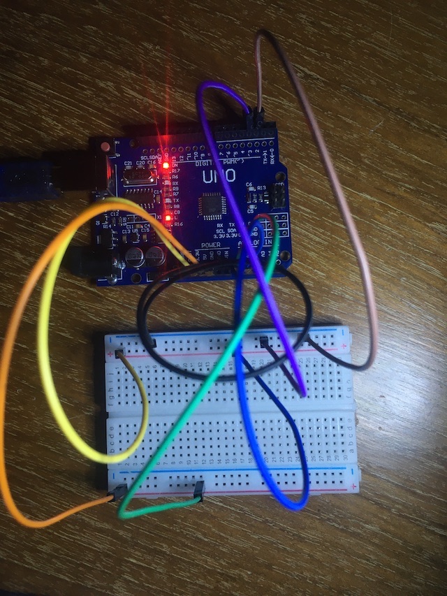
Well, at least the board works, the Arduino IDE on my mac works, etc.....
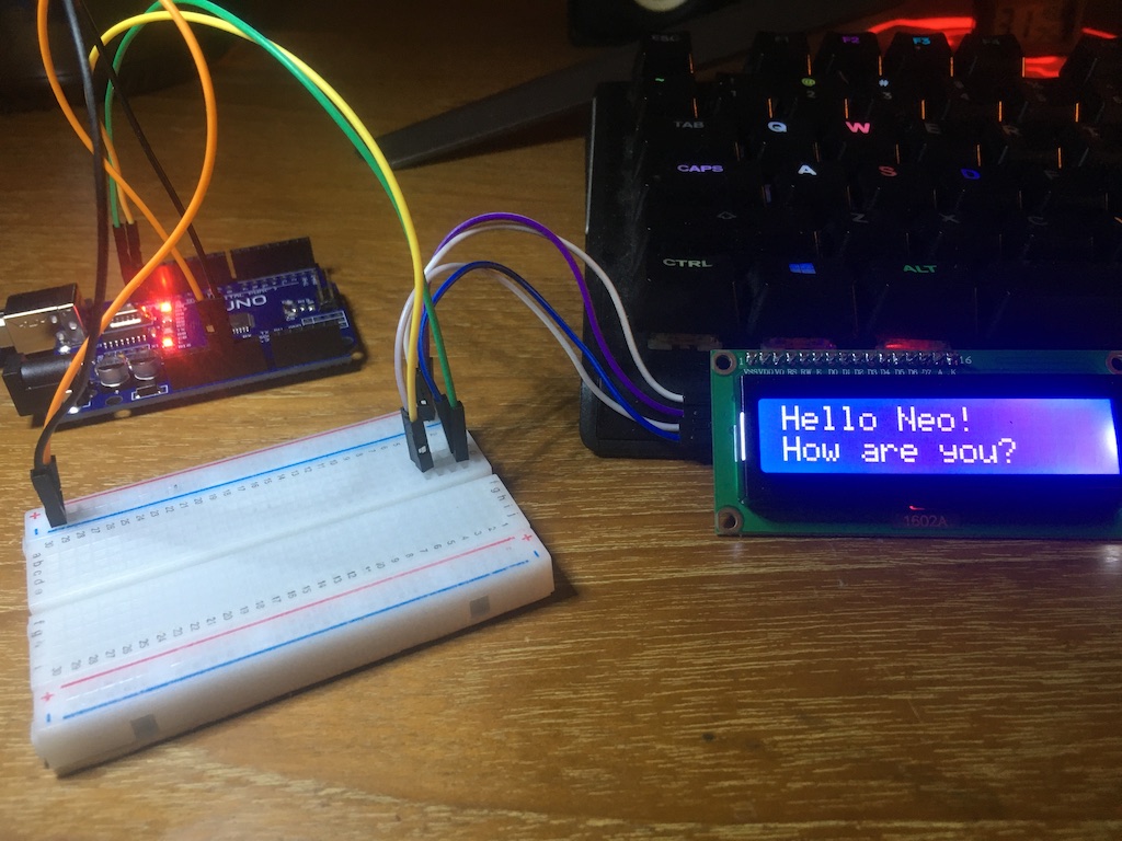
This is gonna be fun, I can tell :slight_smile:

I think I am going to build something for my motorcycle (not sure yet), using a 3G module like this one:

https://www.aliexpress.com/item/32814966264.html

Or maybe I'll do some home automation for fun; so I can control things with SMS messages; or both.

2 Likes

Getting free of the Arduino IDE serial monitor, this python code works.

First, on the mac, import pyserial:

sudo pip install pyserial
macos# cat ard.py

The code:

import serial

ser = serial.Serial(
    port='/dev/cu.usbserial-40',
    baudrate=9600,
    parity=serial.PARITY_NONE,
    stopbits=serial.STOPBITS_ONE,
    bytesize=serial.EIGHTBITS,
    timeout=0)

print("connected to: " + ser.portstr)

# this will store the line
line = []

while True:
    for c in ser.read():
        line.append(c)
        if c == '\n':
            print("Line: " + ''.join(line))
            line = []
            break

ser.close()

Run it:

python ard.py

Output from Arduino on my mac using python to read it:

macos$ python ard.py
connected to: /dev/cu.usbserial-40
Line: 0  - Analog0: 5.00   Analog1: 3.33   Digital2: 0   Digital3: 0

Line: 1  - Analog0: 5.00   Analog1: 3.33   Digital2: 0   Digital3: 0

Line: 2  - Analog0: 5.00   Analog1: 3.33   Digital2: 0   Digital3: 0

Line: 3  - Analog0: 5.00   Analog1: 3.33   Digital2: 0   Digital3: 0

Line: 4  - Analog0: 5.00   Analog1: 3.33   Digital2: 0   Digital3: 0

Line: 5  - Analog0: 5.00   Analog1: 3.33   Digital2: 0   Digital3: 0

Line: 6  - Analog0: 5.00   Analog1: 3.33   Digital2: 0   Digital3: 0

Line: 7  - Analog0: 5.00   Analog1: 3.33   Digital2: 0   Digital3: 0

Line: 8  - Analog0: 5.00   Analog1: 3.33   Digital2: 0   Digital3: 0

Well, this is a bit too easy..... we all can easily set up all kind of sensors in our homes, in our motorcycles or cars, and push the results to a DB on the net and display the results on the web.... even on this site. Or M2M....

Hmmm.

You can do some pretty rinky dink seasonal (Christmas) stuff with an Arduino and strips of LEDs like WS2812b (Google that).

You just need to connect a pin of the strip to 5V, another to GND, and a third to an output pin. I use the FastLED library.
You can program sequences of chasing lights, colour changes, and anything else that you want to do.

I had a problem recently in trying to get outputs (eg, LED flashing) at different frequencies (intervals)) given the single thread available on an Arduino. I got around this by using the modulo function. I'll attach the demo code a wrote for this before I wrote the production stuff.

Also, I got hacked off with trying to program LED flashing (on analogue and/or digital output pins) a number of required times and also fading up or down at the same time. For example, fade a LED up, flash it 4 times, then fade it down. I thought that there had to be an easier way so I wrote "ulcf" (Universal LED Control Function) to allow me to call my requirements in one line of code (or perhaps 2 or 3 calls of the function to get the effect that I want). I'll attach this code to this post too but I'm not saying it's fully debugged but you'll get the drift.

How many electronics engineers are there on this forum who mess about with the likes of Arduino? Show of hands please.

PS. Had to upload files as .txt - site refuses to upload .ino

1 Like

FYI:

If you gzip the .ino file, you can upload it.

:slight_smile:

OBTW, I have a 5 meter strip of LED lights (red, blue, green) I got from Aliexpress for about $4 dollars, including an IR controller. I was thinking to plug the strip directly (omitting the IR controller that came with the strip) into an Arduino project for fun as well. It's currently running off an old car battery on my balcony.

Ok, if you have an LED strip I can send you some code that I wrote for a SMET2 (in the UK that's a Smart Electricity Meter that can be read remotely by the supplier) demonstration. The LED strip was 52 LED's long and demonstrates the supplier sending out a meter read request (3 stages of LED strip light following) and the reverse to demonstrate the data coming back from the smart meter. It was used on a recent demo board at a renewable energy show. Anyway, it's just a demo if you want the code. 52 LED strip (or longer) for full effect.

1 Like

Thanks.

I need to put the meter on the four wire output of the IR controller and get a better understanding of this three light strip (the resistance and the voltage).

At this rate, I will buy that new Rigol 1054Z sooner than later!

In my Aliexpress shopping cart for a few weeks now:

https://www.aliexpress.com/item/32498608008.html
RIGOL DS1054Z 50MHz Digital Oscilloscope 4 analog channels 50MHz bandwidth

@neo..........I've sent you an email with the code attached.

I cannot drop this into the public domain right now, however, anyone else who wants a copy just give me a shout.

1 Like

Here is a similar python script which reads this Arduino test setup:

import serial
ser = serial.Serial("/dev/cu.usbserial-40", 9600)
while True:
     cc=str(ser.readline())
     print(cc[2:][:-1])
macos$ python ard1.py
 - Analog0: 5.00   Analog1: 3.33   Digital2: 1   Digital3: 1
 - Analog0: 5.00   Analog1: 3.33   Digital2: 1   Digital3: 1
 - Analog0: 5.00   Analog1: 3.33   Digital2: 1   Digital3: 1
 - Analog0: 5.00   Analog1: 3.33   Digital2: 1   Digital3: 1
 - Analog0: 5.00   Analog1: 3.33   Digital2: 1   Digital3: 1
 - Analog0: 5.00   Analog1: 3.33   Digital2: 1   Digital3: 1
 - Analog0: 5.00   Analog1: 3.33   Digital2: 1   Digital3: 1
 - Analog0: 5.00   Analog1: 3.33   Digital2: 1   Digital3: 1
 - Analog0: 5.00   Analog1: 3.33   Digital2: 1   Digital3: 1
 - Analog0: 5.00   Analog1: 3.33   Digital2: 1   Digital3: 1

FWIW, the WS2812b LED strip 3 connections are:

5V line to 5V on Arduino
GND line to GND on Arduino
Signal line (LED control) to configured output pin on Arduino via a 100 Ohm resistor.

That's all.

Some web pages talk of a 1000uF capacitor but I didn't need to use one. Everything just worked fine. Of course, your LED strip may be different.

1 Like

Yep, my "cheap from China strip" is four wires.

Note: I may move all the LED project discussion to a different thread.

Anyway, back to this particular testing, have updated my python test script a tiny bit:

macos$ cat ard1.py
import serial
import pathlib
device = "/dev/cu.usbserial-40"
file = pathlib.Path(device)
if file.exists() == False:
    print("Arduino Device "+device+" Does Not Exist")
else:
    ser = serial.Serial(device, 9600)
    while True:
        cc = str(ser.readline())
        print(cc[0:][:-1])

So I guess that 4-wire is 12V supply and 3 red,green, blue wires to ground for each colour.

Hmmm.......That means configuring a separate Arduino pin for each color, I guess.

Place an order for WS2812b strip. Dead easy on Arduno.

Hi Neo...
Apologies for any typos...

Remember to quote your Arduino Programmer version as there have been a great many variations over the years. Mine is Version 0015 and is ancient along with my Arduino Diecimila Boards.
Also your device name could be different for differing versions of your particiular board.

My two Arduinos have differing device names.

Also I have a conversion board that I built on Veroboard that sits over the pins of mine to use RS232 as well as USB if you are interested.

Thanks.

I don't think I need RS232, since I only will be using USB (for programming and dev), Bluetooth, 3G (SMS) and WIFI.

Just ordered two cheap WIFI shields for fun.

https://www.aliexpress.com/item/32278773466.html

The Arduino IDE I am using is version 1.8.10 for macOS.

I have no idea about this board details.... it is some cheap Chinese made UNO board and when I try to pull the board info from the IDE, it says something like "native serial cannot get board info", but I'm not focused on that, as I have a lot of different boards on the way, including some more (Chinese) UNOs, some Nanos and some Pro Minis to deploy on my motorcycle when I get to that stage of fun. This board is just the first one that came; I have a lot more toys on the way for this caper.

LOL, I have 30 pending AliExpress orders, including a RobotKit, OLED modules, many sensors and shields, cases jumpers, nik-nak kits (resisters, caps, diodes,, etc) ...... I plan to connect the Robot in my home to my motorcycle via 3G SMS... all part of the future fun. Maybe do some home automation (I guess they call it IoT NB, these days).

This is really fun... haha . Especially living in Thailand with easy access to all things duty free and Chinese :slight_smile:

PS: Here is the robot kit I plan to modify (when it arrives in a few weeks):

https://www.aliexpress.com/item/4000064621868.html

I could have built the robot much cheaper than the kit price, but "what the heck"... it's all fun!

LOL It was too funny looking, so I had to get it... But I'll do a different discussion thread on Mr. Robot Dude. I need to think how this guy fits into my IoT playground.

OK.

Well, this just about concludes my first test on a "cheap" Chinese Uno board from AliExpress. To summarize lessons learned:

  • The Arduino IDE installs easily and works great on my Mac Pro 2013 running the latest version of Catalina.
  • The cheap Uno board from AliExpress seems to work fine on a simple serial test.
  • Arduino sketch (programming) is really easy and fun.
  • The serial monitor in the IDE worked fine.
  • It was easy to use Python to monitor the same serial port.
  • This is really fun.

So, I'm done with this basic Arduino Uno test and even though I had no prior experience with the Arduino, it was very simple and easy to get started.

I have over 30 open shipments on the way from China to Thailand from AliExpress with many different sensors, kits, displays, shields and modules to test and play with.

Next, I will learn the basics of the (very cheap) 1602A display with the four-pin I2C bus attached to the Arduino Uno, just because I happen to have one in front of me.

Of course, any of my code samples I post will have device addresses unique to my devices. YMMV as I am not writing, modifying or building sketches to be cross-platform compliant (that is not my goal). My goal is to have fun connecting my cars, motorcycles, phones, devices and computers, I guess some would call this IoT, but whatever we call it, it is really fun to be able to get very cheap components from China sent to me with no (or very small) shipping costs from fairly close by (China borders Thailand), duty free with AliExpress. I don't use Banggood (I recently requested Banggood to delete my account); as I do not like their business model and prefer AliExpress because I can chat directly with each seller and ask them questions, especially since I am in the same timezone (for the most part) for normal business hours in China.

My final editorial comment..... I really like AliExpress, and my account shows close to 200 orders to date with AliExpress vendors over the years. The sellers there have always provided good customer service for the most part, far superior to other online sites like this. Banggood, on the other hand, does not permit us to talk directly to sellers, and when we have a problem they approach customer service like a kind of legal inquisition, and so their customer service is, at least to me, horrible. I'm lucky, as a fun-loving electronics hobbyist, to be so close to China, for sure; and it feels good to be getting back into this hobby after so many years focused solely on software.

Arduino ! Better late than never, as they say!

2 Likes

Setting up the 1602 was easy, following this very easy tutorial:

https://dronebotworkshop.com/lcd-displays-arduino/

It looks pretty cool and retro, especially turning the display on and off (which you cannot see in the photos, needs video):

That was fun....

I need to add some retro sounding robot voice.... :slight_smile:

For completeness, here is the sketch I used for the 1602 demo above:

/*
  LCD Display with I2C Interface Demo
  lcd-i2c-demo.ino
  Use NewLiquidCrystal Library
  DroneBot Workshop 2018
  https://dronebotworkshop.com
  Modified by Neo December 2019
  https://www.unix.com
*/

// Include Wire Library for I2C
#include <Wire.h>
// Include NewLiquidCrystal Library for I2C
#include <LiquidCrystal_I2C.h>

// Define LCD pinout
const int en = 2, rw = 1, rs = 0, d4 = 4, d5 = 5, d6 = 6, d7 = 7, bl = 3;

// Define I2C Address - change if reqiuired
const int i2c_addr = 0x27;

LiquidCrystal_I2C lcd(i2c_addr, en, rw, rs, d4, d5, d6, d7, bl, POSITIVE);

void setup()
{

    // Set display type as 16 char, 2 rows
    lcd.begin(16, 2);

    // Print on first row
    lcd.setCursor(0, 0);
    lcd.print("Hello Neo!");

    // Wait 1 second
    delay(1000);

    // Print on second row
    lcd.setCursor(0, 1);
    lcd.print("How are you?");

    // Wait 8 seconds
    delay(8000);

    // Clear the display
    lcd.clear();
}

void loop()
{

    // Demo 1 - flash backlight
    lcd.setCursor(0, 0);
    lcd.print("Do you need unix");
    lcd.setCursor(0, 1);
    lcd.print("or linux help ??");

    delay(3000);
    lcd.clear();

    // Flash backlight 4 times
    for (int i = 0; i < 6; i++)
    {
        lcd.backlight();
        delay(250);
        lcd.noBacklight();
        delay(250);
    }

    // Turn backlight back on
    lcd.backlight();

    // Demo 2 - scroll
    lcd.setCursor(0, 0);
    lcd.print("Visit UNIX.com @");
    delay(4500);
    lcd.setCursor(0, 2);
    lcd.print("www.unix.com  ");
    delay(2500);
    // set the display to automatically scroll:
    lcd.autoscroll();
    // print from 0 to 9:
    for (int thisChar = 0; thisChar < 15; thisChar++)
    {
        lcd.print(' ');
        delay(500);
    }
    // turn off automatic scrolling
    lcd.noAutoscroll();

    // clear screen
    lcd.clear();

    //Delay
    delay(1000);
}

So fun... really... I had no idea playing with the Arduino could be so much fun.

1 Like

I notice from your photos that you are relying on USB power only so far. You have no direct PSU plugged into the Arduino.

So a word of warning as you get into adding stuff to your projects that, before going off on any tangents to investigate why the Arduino crashed, you couldn't upload a sketch because communication was lost, etc, ALWAYS use an independent PSU and see if your problem goes away. It will save you a lot of time investigating "possible faulty Arduino's". Just don't fall for it.

1 Like

Sound advice Dennis, Thanks!

I can plug my bench supply into it. Just lazy to put another piece of gear on my desk, that's all.

Sounds like your advice will save me a lot of time in the future.

Thank You!

Here is a quick test with the same Arduino Uno with the I2C bus and the HC-SRO4 Ultrasonic Ranging Module

and the simple test sketch:

/*
  1602 LCD Display with I2C and HC-SRO4 Demo
  Created by Neo December 2019
  https://www.unix.com
*/
#include <LiquidCrystal_I2C.h>
const int i2c_addr = 0x27;    // bus address from LCD display
LiquidCrystal_I2C lcd(i2c_addr, 2, 1, 0, 4, 5, 6, 7, 3, POSITIVE);
const int trigPin = 9;    //  HC-SRO4 trig
const int echoPin = 10;   //  HC-SRO4 echo
const int maxRange = 400; //  HC-SRO4 max range in cm
const int minRange = 2;   //  HC-SRO4 min range in cm
long duration;
float distanceCm, distanceInch;
void setup()
{
    lcd.begin(16, 2); // Initializes LCD screen and specifies chars (16) and rows (2)
    pinMode(trigPin, OUTPUT);
    pinMode(echoPin, INPUT);
}
void loop()
{
    digitalWrite(trigPin, LOW);
    delayMicroseconds(2);
    digitalWrite(trigPin, HIGH);
    delayMicroseconds(10);
    digitalWrite(trigPin, LOW);
    duration = pulseIn(echoPin, HIGH);
    distanceCm = duration * 0.034 / 2;
    distanceInch = duration * 0.0133 / 2;
    // Set range of HC-SRO4
    if (distanceCm > maxRange || distanceCm < minRange)
    {
        distanceCm = 0;
        distanceInch = 0;
    }
    //first row
    lcd.setCursor(0, 0); // Sets the cursor location
    lcd.print("Dist(cm): ");
    if (distanceCm > 0)
    {
        lcd.print(distanceCm, 1);
        lcd.print("     ");
    }
    else
    {
        lcd.print("         "); // easy clear :)
    }
    // second row
    lcd.setCursor(0, 1);
    lcd.print("Dist(in): ");
    if (distanceCm > 0)
    {
        lcd.print(distanceInch, 1);
        lcd.print("    ");
    }
    else
    {
        lcd.print("         "); // easy clear :)
    }

    delay(200);
}